Free Shipping on qualified items.
Click here for more details


BLOG
High Tensile Fencing, Low Stress Building
There is no better feeling during a fence build than watching your high tensile wires reach tension and create perfectly straight lines that complement the flow of the land they frame. Well-built fence is just as eye catching as it is effective. With a practical price tag, high tensile wire is an excellent choice of material. This blog will help you properly install, terminate, and tension high tensile wire.
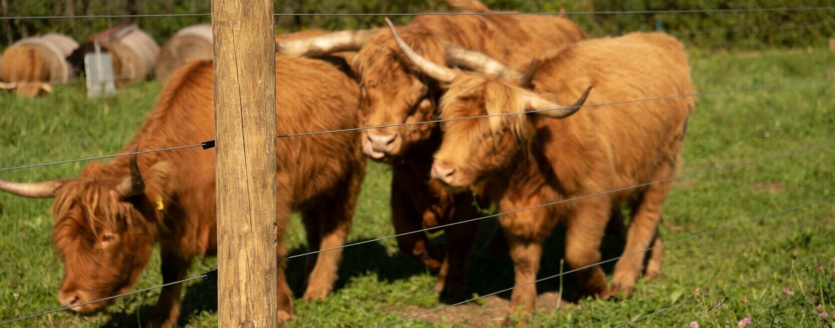
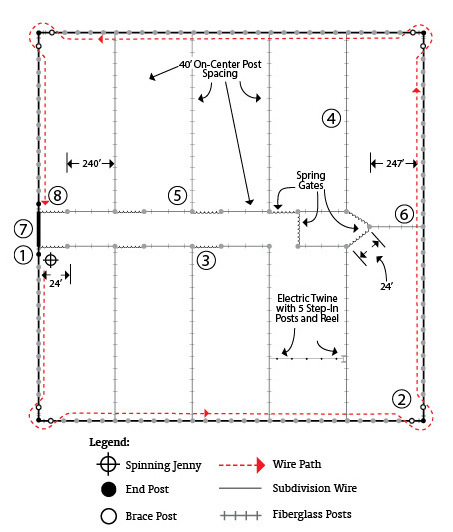
In previous blogs, we covered everything from planning fence layout to constructing H braces. Once these previous phases are complete, wire can be installed in a configuration that fits the context for the fence. Determine how many wires to install and how many need to be electrified. Keep in mind any fence over six strands or above 54” tall should be supported with double H braces at corners, ends, or gates. Placing wires at appropriate heights for livestock or predators will make for a very effective fence. When electric strands are strategically placed at heights to match how intended animals are likely to engage with them, a natural respect for the fence will result after a brief and shocking learning curve.
Cheating is usually frowned upon, but there is an exception when fencing! A cheat stick can be marked at each wire height, eliminating the need to break out the tape measure at every single post. Anything can be used for a cheat stick, such as a 1”x1”, fiberglass rod, a stick, an extra dropper, etc. You may choose to go down the line and mark each post in one shot, or carry the cheat stick with you as you go. Either way, your posts will be marked quickly and accurately.
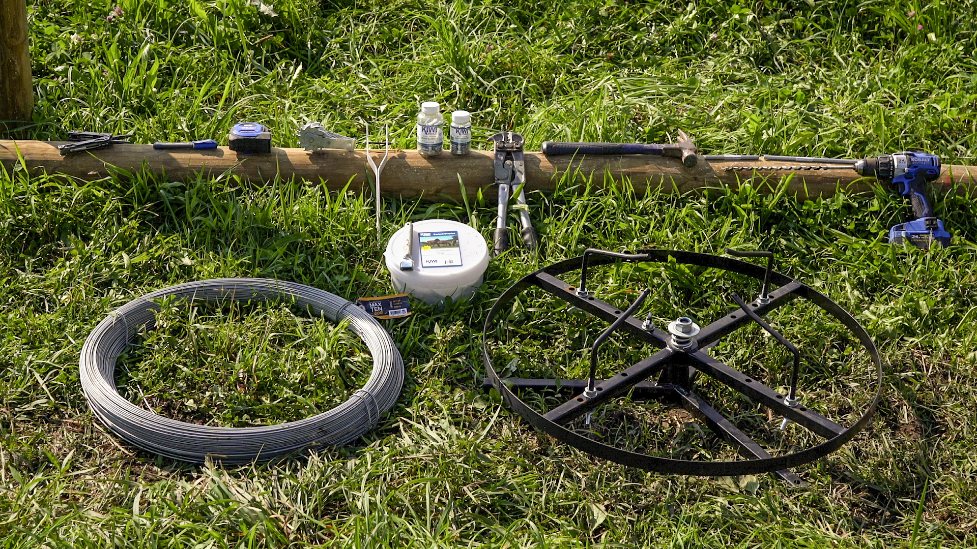
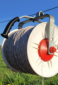
To begin running wire, load your coil onto a spinning jenny. A jenny keeps your coil neat and in order as wire is paid out down the line. You can set the jenny at an end post and walk the wire down the line, or set the jenny in a truck bed or side-by-side (depending on the style of jenny), tie off at an end post, and drive slowly down the line as the jenny pays out wire behind you. To save a step, count posts and braces as you go. Another option when paying out wire on foot, is to place a jenny with wire at each end to eliminate wasted trips and allow wire to be paid out both directions.
Pay out wire until you reach the next end post. Be sure to feed the wire properly around corners or bends, not passing through the middle of H braces or diagonal brace wires.
At this point, the order of operations is important. If the other end of the wire was already terminated at the far end post, this is the time to slide crimps sleeves, wraparound insulators, and tube insulators onto the wire. If the other end of the wire is still on the spinning jenny or isn’t yet terminated, insulators and accessories can be slid on from that end as well. Loading the insulators from either end is acceptable, it may vary based on your preference or convenience of making less trips up and down the fence line at a given phase. The important part of this process is to know how many line post or “tube” insulators are needed based on:
- Your post count (including vertical posts that make up H braces, diagonal H brace wires and one or two extra in case of a miscount)
- How many wraparound insulators are required (take into account end posts as well as any bends or corners in the middle of the run)
- Inserting crimps sleeves in the correct order in regard to insulators. Crimp sleeve is placed on the wire before wraparound.
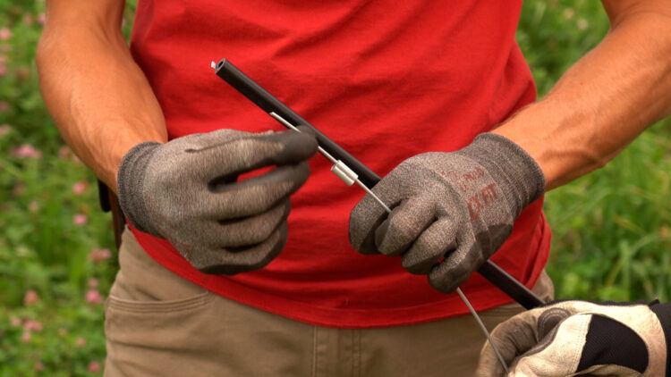
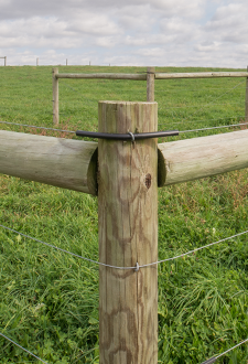
Line post insulators, sometimes referred to as “tube” insulators, are typically 4” long and are slid onto the wire and stapled to each post. They insulate the electric wires from the posts and staples. Some tube insulators have a flat back meant to rest against the post, others are round. Most models of tube insulators have fins that become pinched when a staple is driven over them – creating a holding grip to keep insulators in place. If you are short a tube insulator or need to replace one after the fence is complete and tensioned, spiralator insulators provide the perfect fix. They can be installed after the fact with a quick twist of the wrist. Wraparound insulators come in different lengths – 20” (I40), 24” (I40-24), or 30” (I40-30). These insulators feature an aluminum insert which prevents tensioned wire from cutting through the plastic. Use wraparound insulators to avoid electrified wires making contact with posts as they curve around bends, corners, or end terminations. Larger posts at terminations will require larger wraparounds, like 24” or larger depending on post size.
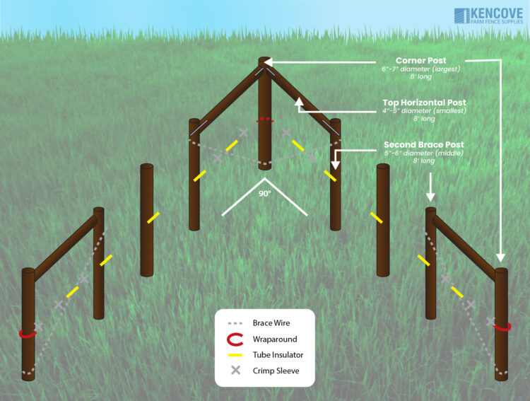
Here is a quick example of the sequence for an “L” shaped fence with twenty line posts total (10 line posts on each side) and a 90° corner (supported by an H brace on each side of the corner post) in the middle. This hypothetical fence terminates at the opposite end and will consist of electrified wires (non-electrified wires do not require insulators).
- Pay out wire while counting how many places require an insulator or crimp sleeve, such as the diagonal brace wires, the secondary vertical support post at the H braces, line posts, a 90° bend at the corner post (adds two tube insulators for the secondary vertical support posts held in place with crimps and one 20” wraparound to the count), and end posts. This configuration would translate into the following material list from one end of the fence to the other:
- initial wraparound insulator with crimp (24” insulator for a full wrap around a 6-7" post).
- Tube insulator for the diagonal brace wire held in place with a crimp on each side
- 3 tube insulators (a vertical H brace post, 10 line posts, and a second vertical H brace post at the corner).
- A wraparound insulator at the 90° corner (20” or 24” depending on size of post).
- Tube insulator for the diagonal brace wire held in place with a crimp on each side,
- 3 tube insulators (a vertical H brace post at the corner, 10 line posts, and a second vertical H brace post at the other end).
- Tube insulator for the diagonal brace wire held in place with a crimp on each side.
- Ending with a crimp and a wraparound insulator at the end post (20” or 24” depending on size of post).
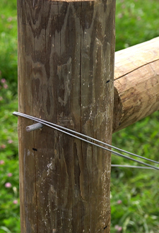
- To begin, at one end post, slide a long crimp sleeve onto the wire first, followed by a wraparound insulator (24” wraparound for a 6-7" diameter post).
- Make a loop around the post with the wraparound insulator in place, leaving enough of a wire tail to crimp. Compress the crimp and trim any excess tail. This makes a complete end termination.
- At the other end post, cut the wire with enough tail to loop around the post, but do not crimp at this time.
- Slide insulators onto the wire in the sequence we previously mentioned.
- With insulators and crimps in the correct order, wrap the wire (which is now inside the wraparound insulator) around the end post and slide tail into the crimp sleeve, pull slack through the crimp sleeve and compress crimp properly. Trim any excess tail.
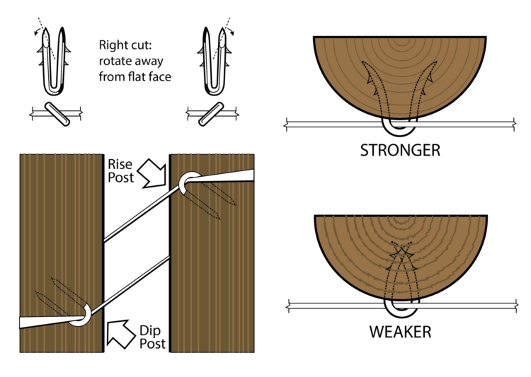
- Now that you have a termination at each end, you can proceed to staple wires/insulators at dips and rises as well as add tension to wires working from the top wire down.
Before adding tension, it may be advantageous to staple each wire at the desired marks at dip or rise posts in order to start the wires at the proper heights. If you were to proceed to fully tension wires without stapling these topography changes, you would find yourself fighting the wire and unable to raise or lower it to your marks.
Tip: Staples are cut differently, and therefore should be installed accordingly. When holding the staple with legs pointing away from you, you will notice the angle cut of one leg facing upward. If it is the right leg, it is a “right cut” staple. In this case, instead of driving the staple vertically, rotate the staple clockwise (for right cut staples) to a 45° angle. This will allow the staple legs to expand in the wood rather than cross over each other.
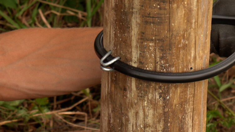
It is also wise to loosely staple the wraparound insulators at corners or bends into place before adding tension. When stapling wraparound insulators, do not straddle the insulator. Instead, drive a staple horizontally above and below the wraparound to keep it from shifting up or down. These staples can be bent over the wraparound after final tension is achieved and you are pleased with the finished product.
Strainers should generally be placed at the midpoint of the fence or at the center of friction if being pulled around corners or bends. Strainers should not be installed next to a dip or rise post. A single, quality strainer is capable of tensioning 4,000ft of linear fence on a level plane. Every change in direction, major dip, or major rise is the equivalent to adding 500ft, per occurrence, to your total distance of fence.
Example: Your fence perimeter measures 3,000ft, but is not a straight line. The layout includes a major dip (+500ft), and 3 bends (+1500ft). The theoretical distance would then be more like 5,000ft and therefore require a second strainer on each line.
As a generalization, plan for a strainer every 2,600ft. This usually covers all bases and is a conservative estimate of strainers needed for a fence build. At least one strainer per strand is required for proper tensioning, even if the fence line is less than 2,600ft – high tensile wire that is only hand-tight will not perform the same as wire that has the mechanical advantage of a strainer.
Once you have located where to place the strainer(s), you will cut the wire and install the strainers one wire at a time, starting with the top wire and working your way down. This will lift the wires as you go, thus minimizing tangles and confusion with multiple slack wires in the mix. Strainers can be installed directly below one another (in a “stacked” vertical arrangement) or staggered (in a stair-step arrangement). There is no difference between these methods other than visual preference. Industry standard recommends installing a tension spring on one strand to act as a tension gauge for the other wires. Tension springs are installed on a standard, open-end strainer and crimped to the wire at the other end of the spring. Indicator marks on the spring make reaching the ideal tension easy. After a few revolutions of the strainer cog, the first mark will be visible, indicating 150lbs of tension. The second mark will indicate 250lbs of tension – the maximum and ideal setting for high tensile wire.
When considering which strainers to use, there are two categories of ratcheting strainers,
- Standard open-end strainers have a hole in the strap where the wire is looped through and crimped on to itself
- Quick-end strainers do not require crimping as they have an internal holding design at the rear of the strap that grips the wire and does not release
Both styles will get the job done, however, many installers are gravitating towards the quick-end strainers for the sake of saving time and a few crimp sleeves along the way. Regardless of how the strainer is secured to the wire, it is loaded the same for both styles. When the strainer is positioned with the spring clip on top, cycle the cog until you can clearly see the hole going through the cog (you’ll hear the clicking sound of the clip and spring as you cycle the cog). Then, feed the wire tail up through the hole of the cog until you’ve pulled the slack out by hand. Fold this excess slack back over the cog so it holds itself in place and does not slide back through the hole. Cut off this excess wire but leave a 6” tail sticking out of the cog. Feed this 6” tail back down through the hole until ¼" to ½" of wire remains protruding from the hole.
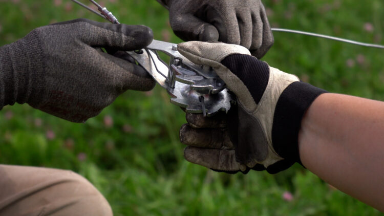
Hold this position and apply tension to the wire by hand while you use a strainer handle to make the initial revolution on the cog. At that point the wire will be secured and there is no need to hold it in place. Add tension and staple wires in a sequence that works for your context and topography. You can then proceed to add final tension while gauging wires with aid from the tension spring. Bracing and posts will “set” over the course of the first twenty-four hours under tension. Assess tension after a full day. An additional click or two on each strainer should suffice at removing any relief that occurred while setting.
Once wires are tensioned and stapled the fence is complete!
As you can see, a well-built high tensile fence is easy to install and maintain. If you follow these steps, your fence will be an asset on your property for years to come. Be safe and happy fencing!