Free Shipping on qualified items.
Click here for more details


BLOG
The Anatomy of an H Brace – Part 2
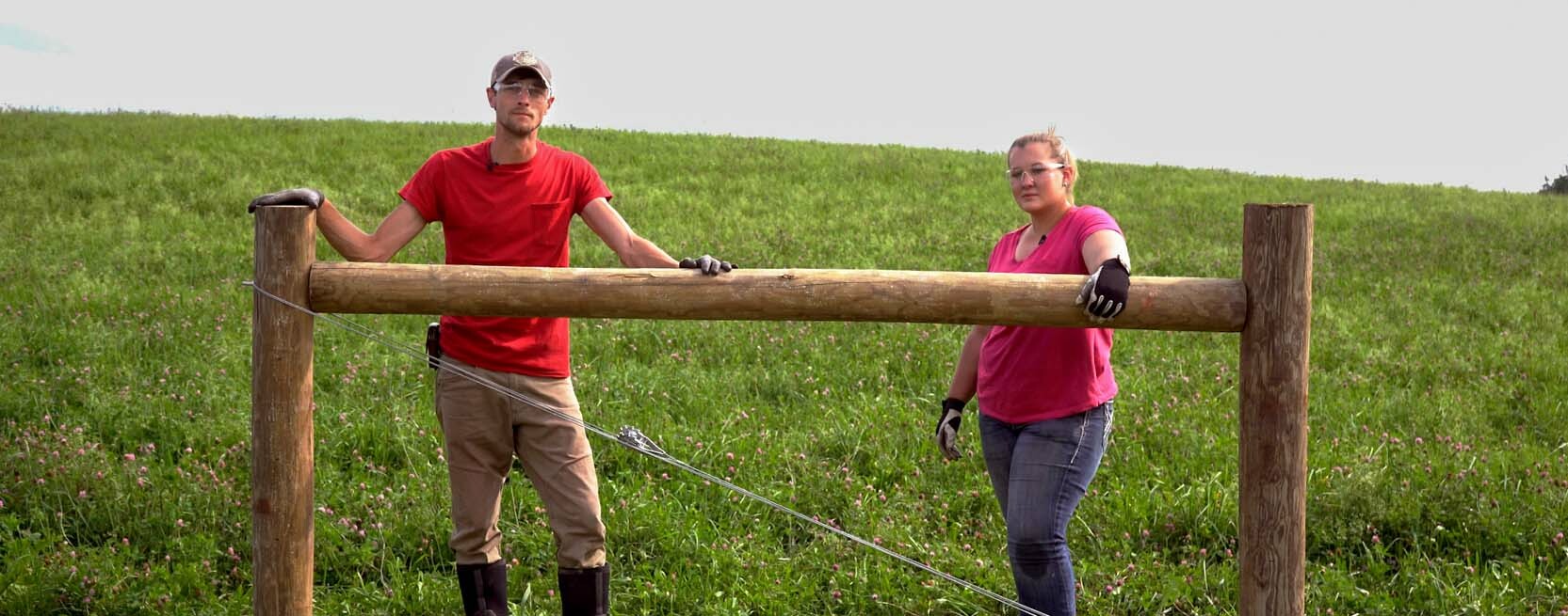
Wire When Ready
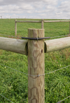
Vertical posts are driven, pins are holding the horizontal post, and brace wire holders are ready for action. The next step is to add brace wire. Brace wire can be the same wire used on the fence line itself. Choose wire that will last! MaxTen 200KSI 12.5 gauge wire is made for a lifetime of service on your farm or ranch. With Class III galvanization and electroplate polish, MaxTen wire refuses to rust. It will resist rust up to three times longer than conventional store-bought wire. The 200KSI wire has a break strength rating of 1,540lbs – twice that of two-strand barbed wire. When building a fence to last a lifetime, choose products that are up to the task.
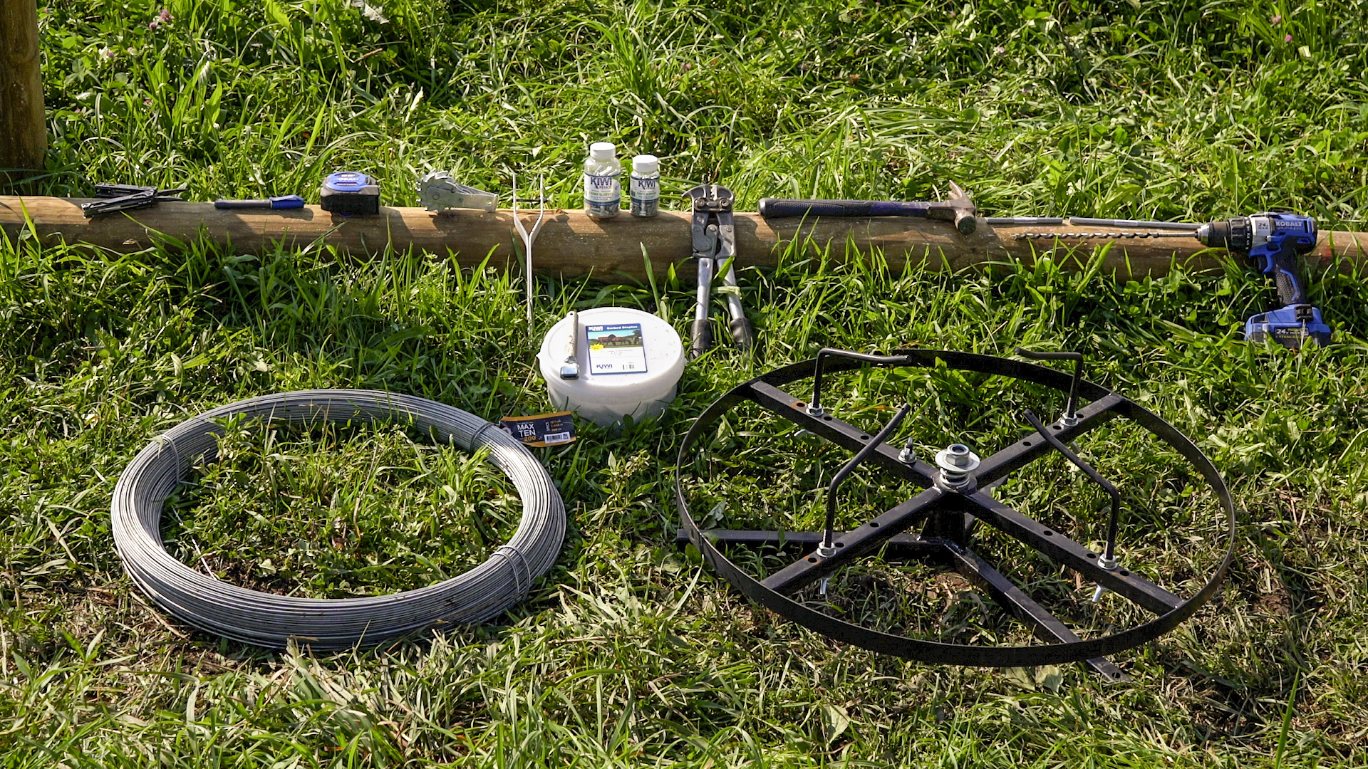
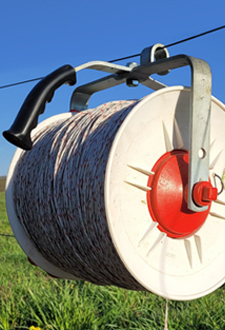
Before even touching the coil of wire, let me ask you one question. Do you have a Spinning Jenny? A Spinning Jenny is a wire holder and payout tool that keeps the wire under control while you feed out wire as needed. Since high tensile wire is coiled, when cut loose of its bands, it will want to expand and make a miserable mess. A spinning jenny prevents this from happening and keeps the wire in an easy-to-use state. Using MaxTen High Tensile wire also makes for easier handling due to being thread-laid, which removes the twist and reduces wire recoil. The benefits of a jenny make it an irreplaceable tool in every high tensile builder’s toolbox. There are many styles of jennys and many ways to use them.
- Single strand jennies that spin on a ground spike (TSJA)
- Self-mounted jennies that can sit on the ground, truck bed, or farm buggy (TSJHH / TSJHD)
- Jennies that can rewind wire during fence removal (TSJRH / TSJRW)
- Multiple strand jennies that mount to 3-point tractor hitches (TSJ4)
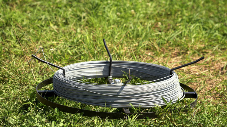
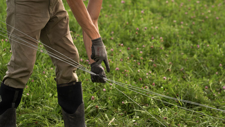
In this situation, let’s assume you are using a single strand jenny and paying out wire on foot. Position the spinning jenny in line with your H brace before adding the weight of the wire coil. To properly load the jenny with wire, rotate the arms towards the inside.
Note: Some jennies have multiple hold down arm mounting positions. Typically, the outer mounting holes are for uncoated high tensile wire, while the inner holes accommodate coated high tensile wire.
Place the coil onto the jenny and turn the arms out so they will now extend over the coil and hold it securely. Ensure your locking & wing nuts are tight, you don’t want a hold down arm rotating around when paying off wire. At this point it is safe to cut the banding from the coil. Before paying out wire locate the two tails. When using MaxTen wire the outer tail is easily located by the tag. The inner is bent over one of the bands. The tail end on the inside of the coil should remain on the inside and may even be fasten to a wing nut or similar feature to keep it in place. The outer tail of the coil is the end you will start paying out. When not in use, this tail can be stuck in the ground or into wire holding features on the jenny itself.
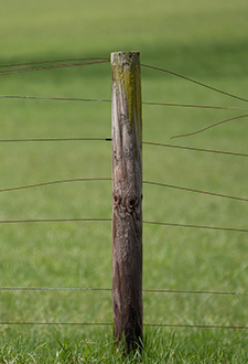
Pay out the wire in a double figure eight pattern, crossing between the two vertical posts and resting on top of the brace pin tail of the secondary vertical post and below the holding staple on the corner/end post on each pass.
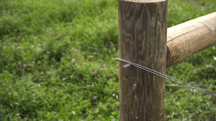
In a proper build, the lower end of the diagonal brace wire will be at the corner/end post. This ensures the pull is directed to where the H brace is strongest (the base of the corner/end post) and that the top of the secondary vertical post is ratcheted snug toward the corner/end post. Once the double figure eight pattern is achieved, work the slack around the posts and account for at least a 6” overlap of wire ends and cut the wire. At the same time, make sure the two strands don’t cross over or under one another at the pin and holding staple, as this could prevent smooth tensioning. The wire ends can be stuck in the ground while you secure the new tail of the coil onto the jenny. Make sure your floating staple is still where you left it on the lower holding staple because the next step is adding tension to the H brace.
Did I Mention Tension?
Tension ties the H brace together and is achieved with the use of a strainer. Quick-end strainers (SASQ) or open-end strainers (SAS) can be used, the difference being the need for crimp sleeves with the open-ended. Quick-end strainers are less involved so here we will describe tensioning with open-end strainers for a full perspective.
Pull your brace wire until the cut ends overlap at the middle of the H brace. At this point, decide which end will be threaded through the strainer strap.
Tip: Positioning the strainer slightly off-center of the brace wire will be advantageous. This gives it clearance of the brace wire intersection for easy tensioning without getting caught on cross wires. Begin with the strainer strap near center, putting the cog end off-center. If installing on the downhill angle of the brace wire, install the strainer with the cog facing downhill. If installing on the uphill angle of the brace wire, install the strainer with the cog facing uphill. Strainers should remain closer to the middle of the H brace, not at the far ends. Doing so will provide maximum clearance away from electric strands as well as ideal tensioning pull.
The strainer strap end of the wire will then be loaded with two short crimp sleeves (C23) or one long crimp sleeve (C2L). Slide these crimp sleeves on to the wire and then make a bend in the tail, leaving about a 4” to 5” tail after the bend. Then, make another bend in the tail at a 45° angle. This angle will make the crimp sleeve(s) slide on easier. Insert this bent tail through the hole on the strainer strap and position the strainer at the original bend.
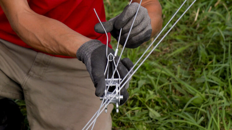
Pull the 45° tail parallel to the main wire, this should make a tear drop shaped loop around the strainer strap. Slide the crimp sleeve(s) so that both the tail and the main wire are joined in the crimp(s). Push the crimp(s) up the wire towards the strainer to make the loop smaller and more inline. Once crimps are in place, use a crimp tool to compress the sleeve(s). Short crimps should receive two compressions and long sleeves should receive three compressions. Kiwi crimp sleeves have incredible holding ability, in fact, wire will break before these crimps fail.
Now, the moment we’ve all been waiting for – tension time. Slide the remaining cut wire through the hole on the strainer cog. You may want to rotate the cog by hand a few times to get a convenient line up for feeding the wire through. Pull any slack up through this hole and bend it over the cog to prevent it from slipping back through. Cut this slack about 6” up from the strainer and pull the 6” tail back through the cog until about a ½" of wire remains protruding from the hole. Use a strainer handle to make the initial few turns of the ratchet. Before continuing to final tension, check that wires are running parallel and look for any cross overs that may pinch while tensioning.
If no wires are crossed and your floating staple is still in place, proceed with tensioning. When approaching the final tension, give the wires a push and tug to move any pinched slack. Work the strainer until the brace wire is taught and snug.
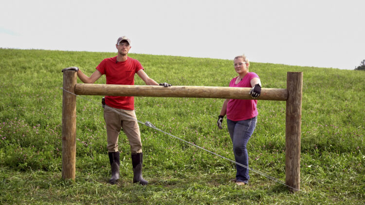
Congratulations, your H brace is complete! Sit back and appreciate your handiwork. But not for too long, the rest of the fence isn’t going to build itself!